Module 11: Competency Test No. 2 Open Book
| Learning Outcomes |
| When you have completed this module, you will be able to:
Within a three hour time limit, complete a written exam and a lab exercise without the aid of a key. |
The AutoCAD 3D book was written with competency based modules. What that means is that you have not completed each module until you have mastered it. The Competency Test module contains multiple choice questions and a comprehensive lab exercise to test your mastery of the set of modules that you completed. There are no answers or keys supplied in a Competency Test module since it is meant to be checked by your instructor. If there are any parts of this module that you have trouble completing, you should go back and reread the module or modules containing the information that you are having trouble with. If necessary, redo as many lab exercises required until you fully understand the material.
If you are completing this book:
- Without the aid of an instructor, complete the written test and the lab exercise.
- In a classroom with an instructor, the instructor will give instructions on what to do after this module has been completed.
Multiple Choice Questions
Select the BEST answer.
- Where would the UCS plane be located if you used the Object UCS icon to select the current UCS?
- It would lie perpendicular to the plane the object selected was on.
- It would be on the WCS.
- It would lie parallel with the current view.
- It would lie on the plane that the selected object was on.
- It would lie perpendicular to the WCS.
- What type of axis must you select to mirror a 3 dimensional object?
- level
- plane
- line
- circle
- point.
- What command is used to polar array an object in 3D space?
- 3DARRAY
- ARRAY
- REVOLVE
- ROTATE
- 3DORBIT
- What is the Z-axis array called in a 3D array?
- Level
- Axis
- Row
- Elevation
- Column
- On what axis will the row be on in a 3D ARRAY?
- X
- Both the X and Y
- Z
- In the negative Z direction
- Y
- How many degrees apart are the XYZ axis in a 2 dimensional isometric drawing?
- 60
- 90
- 120
- 180
- 360
- How must a model be constructed if you want to view it in hidden mode using the VSCURRENT command? Choose the BEST answer.
- As a solid model.
- As a 3D wireframe.
- As a 2D wireframe.
- As a surface model.
- As either a surface or solid model.
- What is the current visual style shown in Figure 11-1?
- 2D wireframe
- 3D wireframe
- Hidden
- Flat
- Gouraud
- What is the current visual style shown in Figure 11-2?
- 2D wireframe
- 3D wireframe
- Hidden
- Flat
- Gouraud
- What type of axis must you select to rotate a 3 dimensional object?
- level
- plane
- line
- circle
- point


Lab Exercise 11-1 OPEN BOOK
| Drawing Name | Template | Units |
| AutoCAD 3D Lab 11-1 | 3D Layout English | Inches |
Step 1
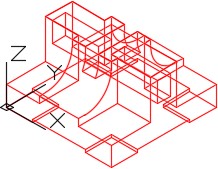
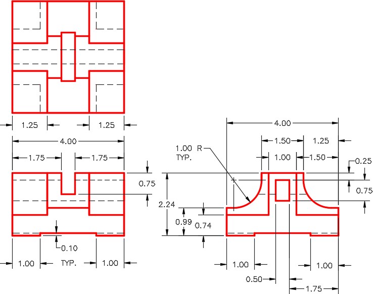
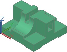
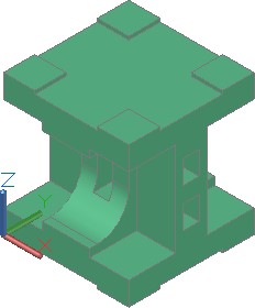
On layer: Model, draw a wireframe model of the object shown in the multiview drawing. Set the current view to SE Isometric. (Figure Step 1A, 1B, 1C, and 1D)
| AUTHOR’S COMMENTS: Draw the right side view first. |
Step 2
Mirror the original model so that the mirrored copy lies on top of the existing model as shown in the figure. (Figure Step 2)
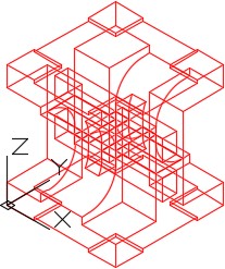
Step 3
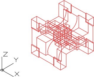
Rotate the model 90 degrees as shown in the figure. Note the location of the WCS in relation to the model, after the rotation. (Figure Step 3)
Step 4
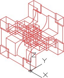
Move the model to locate the front corner on the WCS. (Figure Step 4)
Step 5
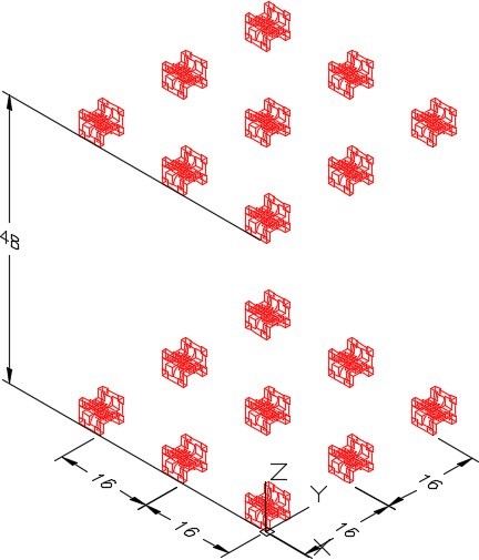
Array the model to match the figure. Keep the location of the WCS in mind when you are executing the array. (Figure Step 5)
Step 6
On layer: Construction, draw a line from absolute coordinates X20,Y100,Z0 to the absolute coordinates X-5,Y100,Z0. (Note that X is negative 5). Before you draw it, ensure that the current UCS is World and keep in mind that the coordinates are absolute so do not use an @.
Step 7
Copy, rotate and locate one of the models at the end of the line you drew in Step 6. Locate it at the absolute coordinates X-5,Y100,Z0 (Note that X is negative 5) as shown in the figure. (Figure Step 7A and 7B)
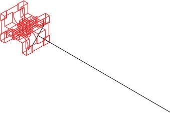
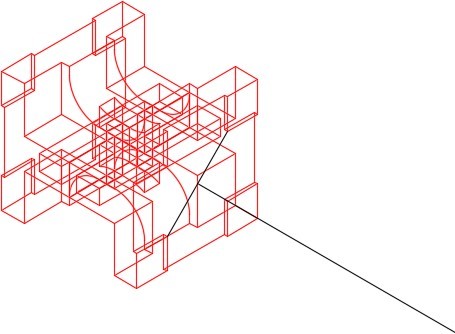
| AUTHOR’S COMMENTS: Draw a diagonal construction line from one corner of the pad on bottom of the model to the corner of the other pad. The line drawn in Step 6, ends at the midpoint of this diagonal line. |
Step 8
Array the model as shown in the figure. (Figure Step 8)
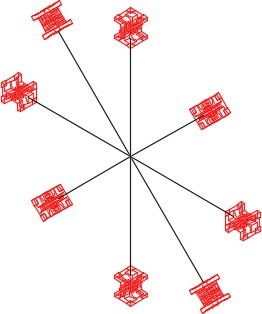
| AUTHOR’S COMMENTS: Ensure that you locate the UCS in the correct location and disable object snap before you preform the array. |
Step 9
Your complete model should match the figure. ( figure Step 9)
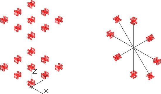
Step 10
Save and close the drawing.
